- 您现在的位置:买卖IC网 > Sheet目录324 > EK-V6-ML631-G-J (Xilinx Inc)VIRTEX-6 HXT FPGA ML631 EVAL KIT
�� �
�
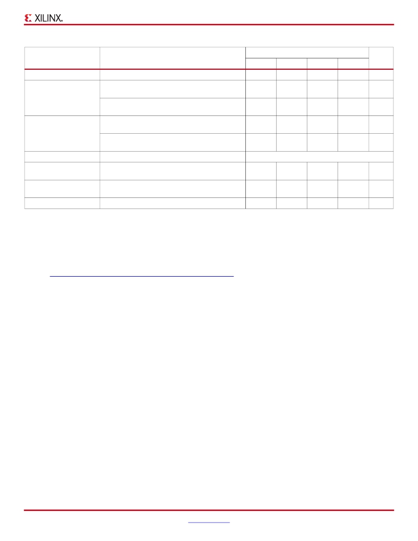
�Virtex-6� FPGA� Data� Sheet:� DC� and� Switching� Characteristics�
�Table� 64:� MMCM� Specification� (Cont’d)�
�Symbol�
�Description�
�-3�
�Speed� Grade�
�-2� -1�
�-1L�
�Units�
�RST� MINPULSE�
�F� PFDMAX�
�Minimum� Reset� Pulse� Width�
�Maximum� Frequency� at� the� Phase� Frequency�
�Detector� with� Bandwidth� Set� to� High� or� Optimized� (9)�
�Maximum� Frequency� at� the� Phase� Frequency�
�1.5�
�550�
�300�
�1.5�
�500�
�300�
�1.5�
�450�
�300�
�1.5�
�450�
�300�
�ns�
�MHz�
�MHz�
�Detector� with� Bandwidth� Set� to� Low�
�F� PFDMIN�
�Minimum� Frequency� at� the� Phase� Frequency�
�Detector� with� Bandwidth� Set� to� High� or� Optimized�
�Minimum� Frequency� at� the� Phase� Frequency�
�135�
�10�
�135�
�10�
�135�
�10�
�135�
�10�
�MHz�
�MHz�
�Detector� with� Bandwidth� Set� to� Low�
�T� FBDELAY�
�Maximum� Delay� in� the� Feedback� Path�
�3� ns� Max� or� one� CLKIN� cycle�
�T� MMCMDCK_PSEN� /�
�T� MMCMCKD_PSEN�
�T� MMCMDCK_PSINCDEC� /�
�T� MMCMCKD_PSINCDEC�
�T� MMCMCKO_PSDONE�
�Setup� and� Hold� of� Phase� Shift� Enable�
�Setup� and� Hold� of� Phase� Shift� Increment/Decrement�
�Phase� Shift� Clock-to-Out� of� PSDONE�
�1.04�
�0.00�
�1.04�
�0.00�
�0.32�
�1.04�
�0.00�
�1.04�
�0.00�
�0.34�
�1.04�
�0.00�
�1.04�
�0.00�
�0.38�
�1.04�
�0.00�
�1.04�
�0.00�
�0.38�
�ns�
�ns�
�ns�
�Notes:�
�1.�
�2.�
�3.�
�4.�
�5.�
�6.�
�7.�
�8.�
�9.�
�When� DIVCLK_DIVIDE� =� 3� or� 4,� F� INMAX� is� 315� MHz.�
�This� duty� cycle� specification� does� not� apply� to� the� GTH_QUAD� (GTH)� to� MMCM� connection.� The� GTH� transceivers� drive� the� MMCMs� at� the�
�following� maximum� frequencies:� 323� MHz� for� -1� speed� grade� devices,� 350� MHz� for� -2� speed� grade� devices,� or� 350� MHz� for� -3� speed� grade�
�devices.�
�The� MMCM� does� not� filter� typical� spread-spectrum� input� clocks� because� they� are� usually� far� below� the� bandwidth� filter� frequencies.�
�The� static� offset� is� measured� between� any� MMCM� outputs� with� identical� phase.�
�Values� for� this� parameter� are� available� in� the� Clocking� Wizard.�
��Includes� global� clock� buffer.�
�Calculated� as� F� VCO� /128� assuming� output� duty� cycle� is� 50%.�
�When� CLKOUT4_CASCADE� =� TRUE,� F� OUTMIN� is� 0.036� MHz.�
�In� ISE� software� 12.3� (or� earlier� versions� supporting� the� Virtex-6� family),� the� phase� frequency� detector� Optimized� bandwidth� setting� is�
�equivalent� to� the� High� bandwidth� setting.� Starting� with� ISE� software� 12.4,� the� Optimized� bandwidth� setting� is� automatically� adjusted� to� Low�
�when� the� software� can� determine� that� the� phase� frequency� detector� input� is� less� than� 135� MHz.�
�DS152� (v3.6)� March� 18,� 2014�
�Product� Specification�
��53�
�发布紧急采购,3分钟左右您将得到回复。
相关PDF资料
EK-V7-VC707-CES-G
VIRTEX-7 VC707 EVAL KIT
EK-Z7-ZC702-CES-G
ZYNQ-7000 EPP ZC702 EVAL KIT
EL1848IYZ-T7
IC LED DRIVR WHITE BCKLGT 8-MSOP
EL7156CSZ
IC DRIVER PIN 40MHZ 3STATE 8SOIC
EL7158ISZ
IC DVR PIN 40MHZ 3STATE 8-SOIC
EL7222CSZ
IC DVR HS DUAL MOSFET 8-SOIC
EL7242CSZ
IC DVR HS DUAL MOSFET 8-SOIC
EL7243CMZ-T13
IC CCD DRIVER DUAL HS 20-SOIC
相关代理商/技术参数
EK-V7-VC707-CES-G
功能描述:VIRTEX-7 VC707 EVAL KIT RoHS:是 类别:编程器,开发系统 >> 通用嵌入式开发板和套件(MCU、DSP、FPGA、CPLD等) 系列:Virtex®-7 标准包装:1 系列:PICDEM™ 类型:MCU 适用于相关产品:PIC10F206,PIC16F690,PIC16F819 所含物品:板,线缆,元件,CD,PICkit 编程器 产品目录页面:659 (CN2011-ZH PDF)
EK-V7-VC707-CES-G-J
功能描述:VIRTEX-7 VC707 EVAL KIT JAPAN RoHS:是 类别:编程器,开发系统 >> 通用嵌入式开发板和套件(MCU、DSP、FPGA、CPLD等) 系列:Virtex®-7 标准包装:1 系列:PICDEM™ 类型:MCU 适用于相关产品:PIC10F206,PIC16F690,PIC16F819 所含物品:板,线缆,元件,CD,PICkit 编程器 产品目录页面:659 (CN2011-ZH PDF)
EK-V7-VC707-G
制造商:Xilinx 功能描述:VIRTEX-7 FPGA VC707 EVALUATION KIT - Boxed Product (Development Kits) 制造商:Xilinx 功能描述:KIT EVAL VIRTEX7 VC707 制造商:Xilinx 功能描述:VIRTEX-7 VC707 FPGA EVAL KIT
EK-V7-VC707-G-J
制造商:Xilinx 功能描述:KIT EVAL VIRTEX7 VC707 JAPAN
EKWF111
功能描述:WiFi/802.11开发工具 WF111 SDIO Eval kit
RoHS:否 制造商:Roving Networks 产品:Evaluation Boards 工具用于评估:RN-171 支持协议:802.11 b/g 频率:2.4 GHz 接口类型:UART 工作电源电压:2 V to 16 V
EKWT11-A
功能描述:蓝牙/802.15.1 开发工具 EKWT11-A
RoHS:否 制造商:Panasonic Electronic Components 产品:Bluetooth Evaluation Kit 工具用于评估:PAN1721 频率:2.4 GHz 接口类型:I2C 工作电源电压:2 V to 3.6 V
EKWT11-E
功能描述:蓝牙/802.15.1 开发工具 EKWT11-E
RoHS:否 制造商:Panasonic Electronic Components 产品:Bluetooth Evaluation Kit 工具用于评估:PAN1721 频率:2.4 GHz 接口类型:I2C 工作电源电压:2 V to 3.6 V
EKWT11i-A
功能描述:蓝牙/802.15.1 开发工具 WT11i A Eval Kit
RoHS:否 制造商:Panasonic Electronic Components 产品:Bluetooth Evaluation Kit 工具用于评估:PAN1721 频率:2.4 GHz 接口类型:I2C 工作电源电压:2 V to 3.6 V